| CE marking directive compliance | Low Voltage Directive, EMC Directive, RoHS Directive |
|---|
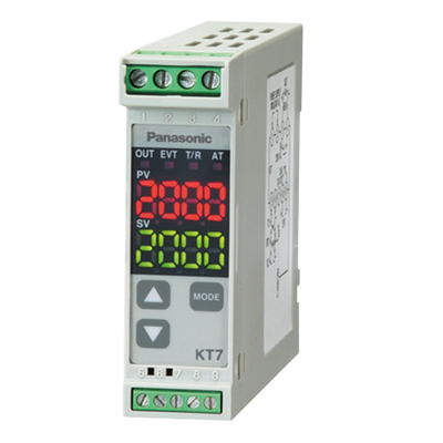
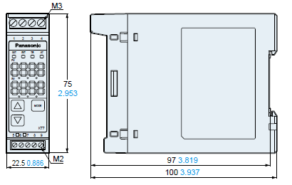
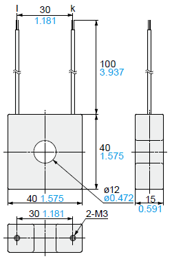
| Size | 22.5×75mm 0.886×2.953 in |
|---|
| Rating | Supply voltage (Must be specified) | 100 - 240V AC |
|---|
| 24V AC/DC |
| Frequency | 50/60Hz |
|---|
| Power consumption | Approx. 6VA |
|---|
| Rated scale | Input type | Input range |
|---|
| Thermocouple | K | -200 to 1370℃(-320 to 2,500 ℉) |
|---|
| -199.9 to 400.0℃(-199.9 to 750.0 ℉) |
| J | -200 to 1,000℃(-320 to 1,800 ℉) |
|---|
| R | 0 to 1,760℃(0 to 3,200 ℉) |
|---|
| S | 0 to 1,760℃(0 to 3,200 ℉) |
|---|
| B | 0 to 1,820℃(0 to 3,300 ℉) |
|---|
| E | -200 to 800℃(-320 to 1,500 ℉) |
|---|
| T | -199.9 to 400.0℃(-199.9 to 7,50.0 ℉) |
|---|
| N | -200 to 1,300℃(-320 to 2,300 ℉) |
|---|
| PL-II | 0 to 1,390℃(0 to 2,500 ℉) |
|---|
| C(W/Re5-26) | 0 to 2,315℃(0 to 4,200 ℉) |
|---|
| RTD | Pt100 | -200 to 850℃(-300 to 1,500 ℉) |
|---|
| -199.9 to 850.0℃(199.9 to 999.9 ℉) |
| JPt100 | -200 to 500℃(-300 to 900 ℉) |
|---|
| -199.9 to 500.0℃(-199.9 to 900.0 ℉) |
| DC Current | 4 to 20mA DC | -1,999 to 9,999,
-199.9 to 999.9,
-19.99 to 99.99,
-1.999 to 9.999 |
|---|
| 0 to 20mA DC |
|---|
| DC Voltage | 0 to 1V DC |
|---|
| 0 to 10V DC |
|---|
| 1 to 5V DC |
|---|
| 0 to 5V DC |
|---|
| | · Scaling and change to the decimal point position is possible for DC current input and DC voltage input.
· DC current input is supported with an externally connected 50Ω shunt resistor (sold separately). |
|---|
| Sensor input | Thermocouple | K, J, R, S, B, E, T, N, PL-II, C (W/Re5-26)
External resistor: Max. 100Ω (max. 40Ω external resistor for B input) |
|---|
| RTD | Pt100, JPt100 3-conductor system (Allowable input conductor resistance for each conductor: max. 10Ωor less) |
|---|
| DC current | 0 to 20 mA DC | Input impedance: 50Ω (Connect 50Ω shunt resistor between input terminals.)
Allowable input current: 50 mA or less (When 50Ω shunt resistor is used) |
|---|
| 4 to 20 mA DC |
|---|
| DC voltage | 0 to 1 V DC | Input impedance: min. 1 MΩ, Allowable input voltage: max 5 V, Allowable signal source resistance: max. 2 kΩ |
|---|
| 0 to 5 V DC | Input impedance: min. 100 kΩ, Allowable input voltage: max 15 V, Allowable signal source resistance: max. 100Ω |
|---|
| 1 to 5 V DC |
|---|
| 0 to 10 V DC |
|---|
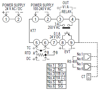
| Control output | Relay contact | (Must be
specified) | 1a |
|---|
| 3 A 250 V AC (at resistive load), 1 A 250 V AC (at inductive load cos ø = 0.4), Electrical life: 100,000 times |
| Non-contact DC voltage | 12+20 V DC, Max. load current: 40mA (Short-circuit protected) |
|---|
| DC current | 4 to 20mADC Load resistance: Max. 550Ω |
|---|
| Alarm output 1 | Open collector, Control capacity: 24V DC 0.1A(Max.) |
|---|
| Alarm output 2 | Not available |
|---|
| Control mode | PID action (with auto-tuning function), PI action, PD action (with manual reset function), P action (with manual reset function), ON / OFF action |
|---|
| Target temperature setting | - |
|---|
| Program control function | - |
|---|
| Indication accuracy | Thermocouple | Within ± (0.2 % + 1 digit) of each input span or within ±2℃ (4℉) whichever is greater However, R or S input; within ±6℃ (12℉) in the range of 0 to 200℃ (32 to 392℉) B input, range of 0 to 300℃ (32 to 572℉): accuracy is not guaranteed K, J, E, T, and N input, less than 0℃ (32℉): within ± (0.4 % ±1 digit) of input span |
|---|
| RTD | Within ±(0.1 % + 1 digit) of each input span or ±1℃ (2℉) whichever is greater |
|---|
| DC current and DC voltage | Within ±0.2% ±1 digit of each input span |
|---|
| Sampling period | 250ms |
|---|
| Hysteresis (ON / OFF) | Thermocouple and RTD: 0.1 to 100.0℃ (℉)
DC current and DC voltage: 1 to 1,000 (The decimal point place follows the selection) |
|---|
| Proportional band | For sensor input range and DC current, DC voltage 0.0 to 110.0% |
|---|
| Integral time | 0 to 1,000 seconds |
|---|
| Derivative time | 0 to 300 seconds |
|---|
| Proportional cycle | 1 to 120 seconds |
|---|
| Allowable voltage fluctuation | When 100-240 V AC: 85-264 V AC, When 24 V AC/DC: 20-28 V AC/DC |
|---|
| Insulated resistance | 500 V DC, Min. 10 MΩ |
|---|
| Breakdown voltage | Between input terminal and power terminal
Between output terminal and power terminal
1.5 kV AC for 1 min. |
|---|
| Malfunction vibration | 10 to 55 Hz (1 cycle/min.), double amplitude: 0.35 mm 0.014 in (10 min. on 3 axes) |
|---|
| Breakdown vibration | 10 to 55 Hz (1 cycle/min.), double amplitude: 0.75 mm 0.030 in (1 hour on 3 axes) |
|---|
| Malfunction shock | X, Y and Z each direction for 5 times 98 m/s2 |
|---|
| Breakdown shock | Same as above, but 294 m/s2 |
|---|
| Ambient temperature | 0 to +50℃ 32 to +122 ℉ |
|---|
| Ambient humidity | 35 to 85%RH (No condensation) |
|---|
| Mass | 150 g approx. |
|---|
| Waterproof | None |
|---|
| Display character height | PV: 7.4 mm 0.291in
SV: 7.4 mm 0.291in
(PV / SV switching display) |
|---|
Option
functions | Heating /
Cooling
control | Relay contact | None |
|---|
Non-contact
voltage | Open collector, Control capacity: 24V DC 0.1A(Max.) |
|---|
Heater burnout alarm
output | Open collector, Control capacity: 24V DC 0.1A(Max.) |
|---|
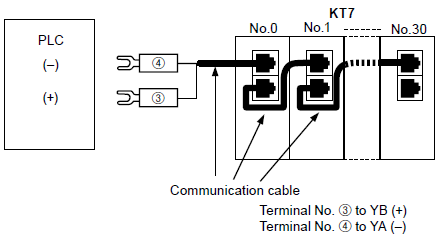
| Communication function | Please refer below to “Communication Function Overview”. |
|---|
| Accessories | Mounting frame / Mounting bracket | - |
|---|
| Terminal cover | - |
|---|
| Rubber gasket | - |
|---|